What is Distributed Control System DCS?
In recent years, the use of smart devices and field buses makes distributed control system (DCS) to be prominent in large and complex industrial processes as compared to the former centralized control system. This distribution of control system architecture around the plant has led to produce more efficient ways to improve reliability of control, process quality and plant efficiency.
Nowadays, distributed control system has been found in many industrial fields such as chemical plants, oil and gas industries, food processing units, nuclear power plants, water management systems, automobile industries, etc.
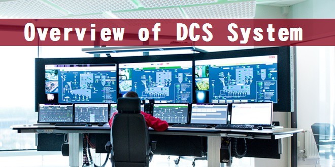
What is DCS System?
A distributed control system (DCS) is a specially designed automated control system that consists of geographically distributed control elements over the plant or control area.
It differs from the centralized control system wherein a single controller at central location handles the control function, but in DCS each process element or machine or group of machines is controlled by a dedicated controller. DCS consists of a large number of local controllers in various sections of plant control area and are connected via a high speed communication network. In DCS control system, data acquisition and control functions are carried through a number of DCS controllers which are microprocessor based units distributed functionally and geographically over the plant and are situated near area where control or data gathering functions being performed as shown in the figure above. These controllers able to communicate among themselves and also with other controllers like supervisory terminals, operator terminals, historians, etc.
 In DCS control system, data acquisition and control functions are carried through a number of DCS controllers which are microprocessor based units distributed functionally and geographically over the plant and are situated near area where control or data gathering functions being performed as shown in the figure above. These controllers able to communicate among themselves and also with other controllers like supervisory terminals, operator terminals, historians, etc.
Distributed individual automatic controllers are connected to field devices such as sensors and actuators. These controllers ensure the sharing of gathered data to other hierarchal controllers via different field buses. Different field buses or standard communication protocols are used for establishing the communication between the controllers. Some of these include Profibus, HART, arc net, Modbus, etc.
DCS is most suited for large-scale processing or manufacturing plants wherein a large number of continuous control loops are to be monitored and controlled. The main advantage of dividing control tasks for distributed controllers is that if any part of DCS fails, the plant can continue to operate irrespective of failed section.
You may also read: What Exactly Is A Smart Grid?
Architecture of Distributed Control System
As the name suggests, DCS has three main qualities. The first one is the distribution of various control functions into relatively small sets of subsystems, which are of semiautonomous, and are interconnected through a high speed communication bus. Some of these functions include data acquisition, data presentation, process control, process supervision, reporting information, storing and retrieval of information.
The second attribute of DCS is the automation of manufacturing process by integrating advanced control strategies. And the third characteristic is the arranging the things as a system. DCS organizes the entire control structure as a single automation system where various subsystems are unified through a proper command structure and information flow.
These attributes of DCS can be observed in its architecture shown in the diagram below. The basic elements comprised in a DCS include engineering workstation, operating station or HMI, process control unit or local control unit, smart devices, and communication system.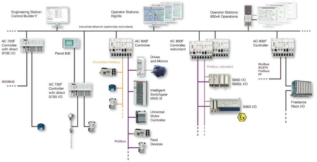

Engineering Workstation:
It is the supervisory controller over the entire distributed control system. It can be a PC or any other computer that has dedicated engineering software (for example, control builder F engineering station in case of ABB freelance distributed control system).
This engineering station offers powerful configuration tools that allow the user to perform engineering functions such as creating new loops, creating various input and output points, modifying sequential and continuous control logic, configuring various distributed devices, preparing documentation for each input/output device, etc.
You may also read: What is PID Controller & How it Works?
Operating Station or HMI
This is used to operate, monitor and control plant parameters. It can be a PC or any other monitoring device that has a separate software tool on which operator can view process parameter values and accordingly to take control action. For instance, it is a DigiVis software tool that can run on a simple PC-environment in case ABB DCS.
Operating stations can be a single unit or multiple units where a single unit performs functions like parameter value display, trend display, alarming, etc. while multiple units or PCs performs individual functions such as some PCs display parameters, some for trend archives, some for data logging and acquiring, etc.

Process Control Unit of DCS
It is also called as a local control unit, distribution controller, or process station. A distributed control system can consists of one or more process stations that can be extended with different types of I/O units. These controllers consist of a powerful CPU module, field bus or communication module with extended field bus capability and either direct or remote connected I/Os.
The field devices like sensors and actuators are connected to I/O modules of this unit. Some field devices can be directly connected to field bus (such as Profibus) without any I/O module, which can be termed as smart field devices.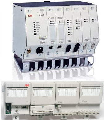

These units acquire the information from various sensors via input module, analyze and process it based on the control logic implemented and sends the output signals via output modules to have control on actuators and relays.
In case of <rel “nofollow” a href=”http://new.abb.com/control-systems/essential-automation/freelance/controller/ac800f” target=”_blank”>ABB DCS, AC800F module (consider, for instance) acts as process station, which is responsible for acquiring and controlling the data from the process. This unit consists of a power supply along with CPU section, Ethernet section, Profibus section and remote communication interface unit for I/Os interfacing as shown in the figure where first module is AC 800F unit and other one is remote I/O (also called as communication interface module).
YOu may also read: An Overvew of DC Drives
Communication System
The communication medium plays a major role in the entire distributed control system. It interconnects the engineering station, operating station, process station and smart devices with one another. It carries the information from one station to another. The common communication protocols used in DCS include Ethernet, Profibus, Foundation Field Bus, DeviceNet, Modbus, etc.
It is not mandatory to use one protocol for entire DCS, some levels can use one network whereas some levels use different network. For instance, consider that field devices, distributed I/Os and process station are interconnected with Profibus while the communication among engineering station, HMI and process station carried though Ethernet as shown in the figure below.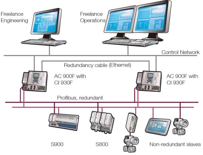

The major advantage of DCS is the redundancy of some or all levels of the control area. Most of the cases critical processes are installed with redundant controllers and redundant communication networks such that problem in main processing line should not affect the monitoring and control functions because of the redundant processing section.
You may also read: Overview of AC Drives and VFD
Smart or Intelligent Devices
The intelligent field devices and field bus technology are advanced features of DCS technology that replaces traditional I/O subsystems (I/O modules). These smart devices embed the intelligence required for simple sensing and control techniques into the primary sensing and actuating devices. And hence it replaces the need for a DCS controller to perform routine sensing and control process.
These field devices can be directly connected to field bus so that sourcing of multiple measurements to the next higher level control station is possible via digital transmission line by eliminating extraneous hardware such as local I/O modules and controllers.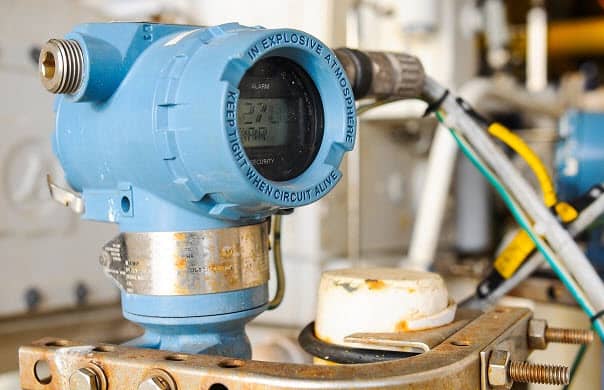

Working & Operation of DCS System
The operation of DCS goes like this; Sensors senses the process information and send it to the local I/O modules, to which actuators are also connected so as to control the process parameters. The information or data from these remote modules is gathered to the process control unit via field bus. If smart field devices are used, the sensed information directly transferred to process control unit via field bus.

The collected information is further processed, analyzed and produces the output results based on the control logic implemented in the controller. The results or control actions are then carried to the actuator devices via field bus. The DCS configuring, commissioning and control logic implementation are carried at the engineering station as mentioned earlier. The operator able to view and send control actions manually at operation stations.
you may also read: Power Distribution in Industries
Difference between SCADA and DCS (DCS vs SCADA)
Although both DCS and SCADA are monitoring and control mechanisms in industrial installations, they have different goals. There exist some commonality between DCS and SCADA in terms of hardware and its components, however, there are certain requirements by the end applications that separates a robust and cost-effective DCS from the viable SCADA system. Some of the differences between DCS and SCADA are listed below.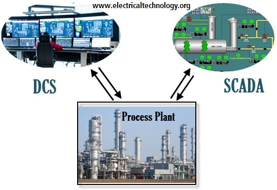

- DCS is process oriented, whereas SCADA is data-gathering oriented. DCS emphasizes more on control of the process and it also consists of supervisory control level. And as a part of doing so, it presents the information to the operator. On the other hand, SCADA concentrates more on acquisition process data and presenting it to the operators and control centre.
- In DCS, data acquisition and control modules or controllers are usually located within a more confined area and the communication between various distributed control units carried via a local area network. SCADA generally covers larger geographical areas that use different communication systems which are generally less reliable than a local area network.
- DCS employs a closed loop control at process control station and at remote terminal units. But in case of SCADA there is no such closed loop control.
- DCS is process state driven where it scans the process in regular basis and displays the results to the operator, even on demand. On the other hand, SCADA is event driven where it does not scan the process sequentially, but it waits for an event that cause process parameter to trigger certain actions. Hence, DCS does not keep a database of process parameter values as it always in connection with its data source, whereas SCADA maintains a database to log the parameter values which can be further retrieved for operator display and this makes the SCADA to present the last recorded values if the base station unable to get the new values from a remote location.
- In terms of applications, DCS is used for installations within a confined area, like a single plant or factory and for a complex control processes. Some of the application areas of DCS include chemical plants, power generating stations, pharmaceutical manufacturing, oil and gas industries, etc. On the other hand SCADA is used for much larger geographical locations such as water management systems, power transmission and distribution control, transport applications and small manufacturing and process industries.
In spite of these major differences, the modern DCS and SCADA systems come with common standard facilities while dealing process plant automation. However, the choice between DCS and SCADA depends on its client and end application requirement. But if the client choice between these two, by gaining equal requirement from the process, DCS is the economical choice as it help to reduce the cost and offer better control.
DCS Systems from Different Vendors
Some of the available DCS systems include
- ABB- Freelance 800F and 800 xA
- Yokogawa- Centum CS 3000 and 1000
- Honeywell-TDC 3000
- Emerson- Delta V Digital Automation
- Siemens- Simatic PCS 7
- Allen- Bradley- NetLinx


